Turbocharging is a huge part of the automotive world. Especially in the last decade, turbocharged applications in both performance aftermarket and auto manufacturers have grown significantly. Turbocharging takes wasted exhaust energy from an internal combustion engine and uses it to produce more power than you can achieve without it. It truly is a massive feat of engineering that has given automobiles of all kinds the ability to perform at higher levels of power and efficiency, among many other benefits. We are not going to go into turbocharger theory, go over the history of turbocharging, or talk about how they work in this article. There are so many other resources that cover this topic and many of them are written by extremely qualified individuals and engineers.
Because of our involvement in the aftermarket side of the turbocharging world, we want to educate those of you that are interested in upgrading your turbo to a higher flowing, higher performing version. We get tons of questions surrounding this subject and I know this will help many of you that aren’t sure which direction to take or what the physical parts that are being changed are. We’ll discuss more about aftermarket turbocharging in later parts but Part 1 will contain basic information about what parts of a turbocharger are important and why you need to consider all these details when selecting your turbo upgrade path. As always, please email, message, or call us for any further questions on how to properly achieve your goals with your car! We’re here to help you!!
Here is a list of the most important parts of a turbocharger and how they relate to your desired setup. How to choose the right turbo setup is right around the corner with a little bit of reading!
Compressor Housing
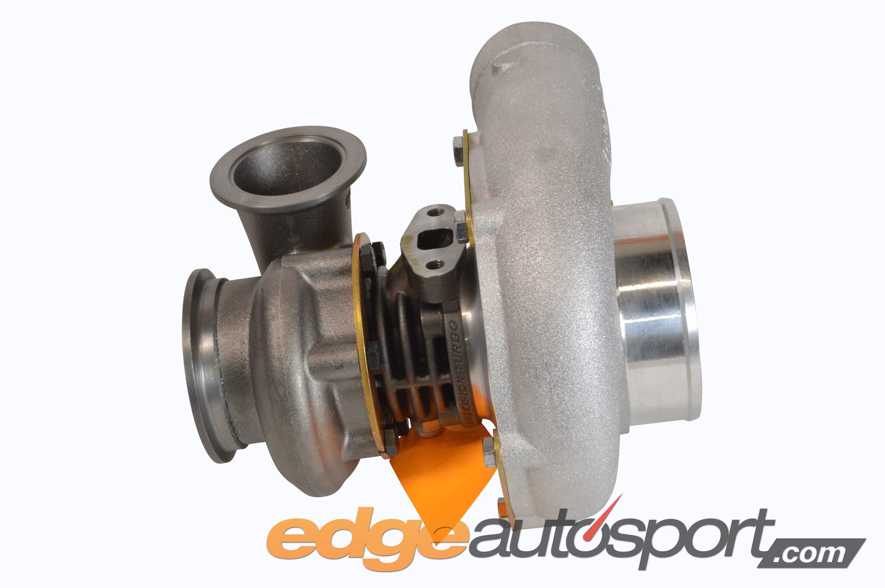
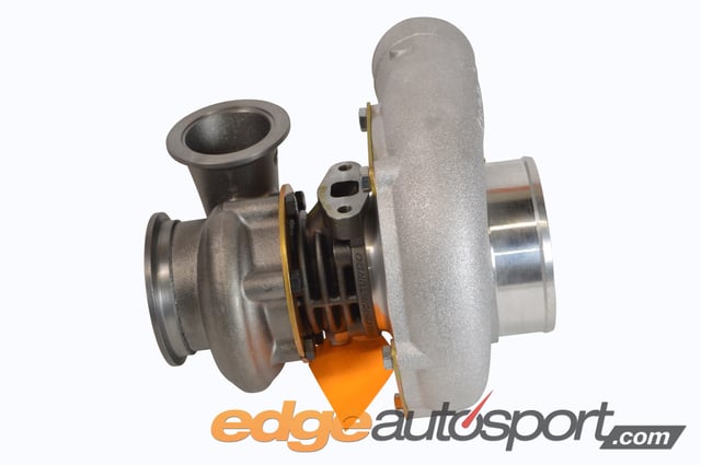
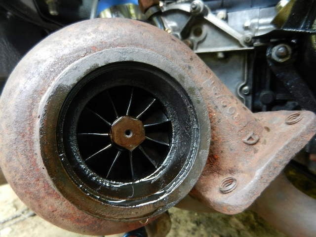
The compressor housing of the turbocharger is the section that directs intake air in and out of the housing in a radial direction (almost all automotive turbos use this method), meaning the opposite direction of the axis of the wheel, and into the engine. The compressor housing can often be called the “cold” side of the turbo. The “hot” side is a common turbine housing reference which will be covered later. This is because it is taking in fresh, cooler air from the atmosphere (although it is not cold air being sent to the engine, it’s still relatively hot after being compressed). Simply put, the compressor housing houses the compressor wheel and directs the airflow in and out of the turbo. The compressor inlet is where the air is pulled in and the compressor outlet is where the compressed air is then sent out.
 |
 |
|
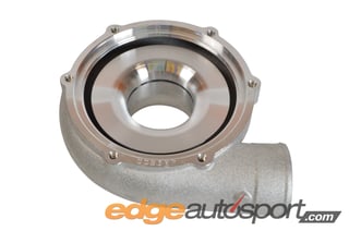
The inside of the compressor housing of a |
The outside of a Precision 6262 turbo compressor housing. |
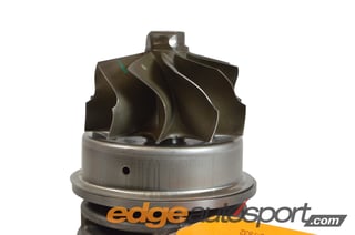
Compressor Wheel
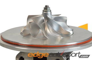
The compressor wheel is the device inside the compressor housing that is drawing air into the compressor housing and sending it to the engine. Atmospheric “air” is made up of various gases, including mainly oxygen and can be compressed, meaning you can shove more air in the same volumetric space than what was there before. For a car’s engine, that means a turbo can create more air in a specific space than what is in the atmosphere and send it into the engine. The more air an engine can take in and mix with fuel, the more power it has the ability to make. It’s basically a highly engineered fan blade. Many turbocharger wheels have the ability to spin well over 150,000 rpms!!
 |
 |
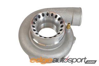
| A side view of a fairly large, high performance compressor wheel. |
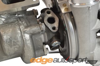
Turbine Housing
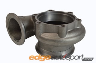
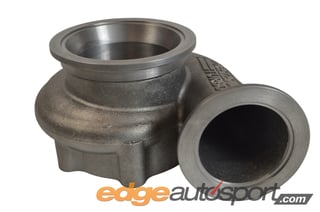
On the opposite side of the turbo’s compressor wheel, another “fan blade”, if you will, is connected through the center of the turbo and spins at the exact same speed because it is connected by a shaft in the middle. The turbine housing is where the exhaust gases collect as they leave the engine and are guided through to the turbine wheel, then sent out of the turbine housing. It’s basically doing the same thing as the compressor housing as far as moving air, except it is doing it with exhaust gases. And instead of pulling air in, the exhaust is being pushed through the housing to force the turbine wheel to spin. The SIZE of the turbine housing has a lot to do with how the turbocharger performs, specifically how quickly it achieves the desired boost pressure level and how well it flows at higher RPMs. Many of the same size turbos come with different size options for the turbine housing to manipulate how the turbo performs based on what type of racing or driving you are doing. We’ll get more into this after Part 1.
 |
 |
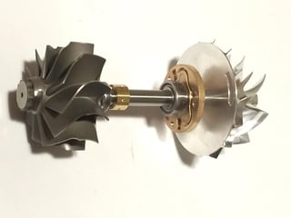
Turbine Wheel
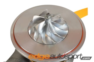
The turbine wheel is connected to the compressor wheel by a shaft. The exhaust gases leaving the engine enter the turbine housing, where the turbine wheel is located inside of, and spins the wheel. The exhaust gases carry much more heat energy and higher pressure which help drive the wheel to spin very quickly, ultimately spinning the other side of the turbo where it pulls in and compresses the air.
 |
 |
| An exposed turbine wheel with no turbine housing assembled. |
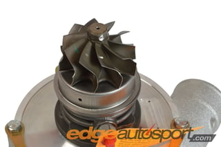
CHRA – Ball Bearing and Journal Bearing
CHRA is an acronym for Center Housing and Rotating Assembly. This is the center section of the turbo that houses the bearings and center shaft. It allows the compressor and turbine wheels to spin as freely as possible but keeping the center axle connecting the two wheels as stable as possible to prevent movement. If you’ve ever felt what 20psi of air feels like, you know even that much has quite a punch to it when released, let alone 30 or 40psi. If you thought that was a lot, the exhaust side, especially if it’s heavily restricted, is seeing much higher pressure than that, something triple or quadruple the amount. All the while, the wheel is spinning 100,000 rpms or more. If anything moves or goes wrong while the wheels are spinning at that speed, you can count on a catastrophic turbo failure, sometimes even damaging other parts as it sends shrapnel through the intake and/or exhaust system. During the turbo’s operation, there is oil and coolant flowing through this CHRA section in order to lubricate the bearings and cool the center of the turbo since it operates in extreme heat and high spinning revolutions.
 |
 |
| This CHRA is from a BorgWarner EFR series turbo. The compressor housing is on the right, turbine housing on the left, and CHRA in the center. |
Shown here is the rotating assembly inside the CHRA. This is a unique setup with journal and ball bearings. |
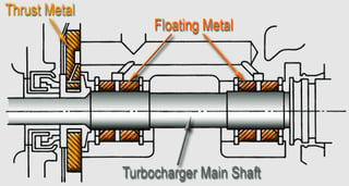
Journal Bearing CHRA
A journal bearing CHRA features a journal style bearing where the shaft that joins the compressor and turbine wheels together spins inside of a sleeve. The sleeve has holes in it at multiple points to allow oil in and create a lubrication barrier for the shaft to spin inside of. There is also a thrust bearing that prevents movement from side to side during heavy load operation while the turbine wheel is forcing its way back towards the turbo under high boost. It also helps stabilize the compressor wheel to not only prevent movement but also keep the turbo mechanically efficient which means flowing as much air as possible. Journal bearings typically require a much greater amount of oil since they are more reliant on it for cooling and the larger contact area of the bearing to the shaft. It also helps absorb much of the force being applied to the shaft during operation, sort of like a cushion.
 |
 |
| Photo courtesy of airpowersystems.com. | Photo courtesty of Turbo by Garrett. |
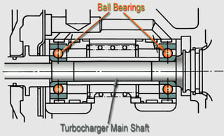
Ball Bearing CHRA
A ball bearing CHRA is a newer style (although not new, in general). This style uses balls located inside of bearing cages that spin and move along with the shaft. They are not physically connected to the shaft so they move on their own but they provide much less surface area to move on as they spin and move inside of the bearing cage. This allows much less friction as the center shaft spins which ultimately means less drag as the shaft spins. This has helped turbo manufacturers create turbos with faster all around response including initial spool going from no boost to full boost and transient response which happens during gear shifts, partial throttle to full throttle, etc.
 |
 |
| Photo courtesy of airpowersystems.com. | Photo courtesty of Turbo by Garrett. |
In later parts, we’ll not only revisit the benefits of some of these turbocharger components but we’ll extend further into basic principles of selecting a turbocharger. We’ll talk about wastegates, boost controllers, blowoff/bypass valves, flange options and dimensions, and intercoolers.
Topics:


.jpg)


